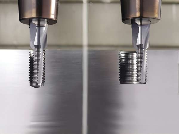
The following are the detailed steps and working process of the milling machine:
Part Design
The process begins with the design of the part to specify the desired requirements. For CNC milling machines, the design process includes programming and generating machine instruction files using computer-aided manufacturing (CAM) software. For manual milling machines, the part design can be a basic blueprint containing various dimensions.
Machine Setup
Before machining can begin, the milling machine needs to be properly set up. This includes adjusting various settings. For CNC milling machines, the programme is transferred to the control system. For manual milling machines, various parameters of the machine are adjusted as needed.
Workpiece clamping
The workpiece is securely clamped to the table. Make sure that all clamps and fixtures are secure. Any loose fixtures will cause vibration, which may result in poor milling quality or even damage to the part.
Milling
After the workpiece is secured and the machine is set up, the milling process begins. The rotating tool gradually removes material from the surface. The path and shape of material removal depends on the type of milling tool and the desired shape. The rate at which the tool moves into the workpiece is called the feed rate.
Part Inspection
Once the milling cycle is complete, the part is removed and inspected for quality. If the quality meets the required standards, the part is removed and sent for further processing. If further processing is required, the part will undergo another milling cycle.

Proficiency in the use of milling machines requires knowledge of various parameters associated with these machines. These parameters include:
RPM: RPM is the speed at which the cutting tool rotates. It is expressed as n in revolutions per minute (rpm).
Tool diameter: the diameter of the tool is expressed as Dc in millimetres (mm). Larger diameters result in higher material removal rates. However, high-precision machining usually uses smaller tools.
Cutting Speed: Cutting speed is the linear velocity of the cutting tool. It is expressed as Vc in metres per minute (m/min). It is calculated by the following formula:
Vc=π×Dc×n/1000
Feed Speed: Feed speed is the rate of movement of the cutting tool into the workpiece. It is expressed as Vf. It is calculated by the following formula:
Vf=Ff×n
where Ff is the feed per revolution.
Depth of Cut: The depth of cut is the depth of penetration of the tool in the z-axis direction. Larger depths result in higher tool wear. The depth of cut is expressed as ap.


