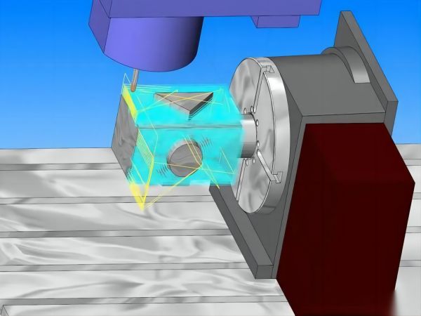
G-code plays a vital role in CNC programming. automation of CNC machining is accompanied by the interpretation of G-code. CNC machines cannot understand the language of dialogue. They use a set of specialised machine language commands. Programmers compile these commands into G-code files to instruct the CNC machine how to operate.
The CNC programming microcontroller is pre-programmed with the meaning of each G-code command. Therefore, when the microcontroller reads a specific command, it immediately knows what to do. If any G-code command is outside the CNC microcontroller‘s dictionary, the command will not work.
G-code commands are used in conjunction with their M-code counterparts. the G-code controls the CNC machine motion, while the M-code controls the CNC machine‘s functional processes, such as coolant flow or tool change. the M-code and G-code commands can be used together to form a complete CNC programming file.
There are over a hundred G-code commands used for CNC programming. Most G-codes are common to every CNC programming operation. However, certain G-codes are specific to types of operations such as milling, turning, drilling, and so on.
The list of G-codes may vary between CNC manufacturers.
Not all G-codes are supported on every machine. In addition, machines with unique features or multi-axis machining capabilities may have additional G-codes. The manufacturer may provide instructions on G-codes for CNC programming in the reference yearbook that comes with the machine.

CNC Motion and Travel
The following codes are used to control motion and tool paths in CNC programming:
G00: Machine Rapid Traverse
The rapid traverse command moves the tool from one point to another without cutting the material. These movements are done at the highest possible speed. Therefore, the rapid traverse command does not require a feed rate. It requires X-, Y-, and Z-axis position coordinates.
G01: Machine Linear Interpolation
Linear interpolation moves the tool along a straight line from one point to another. The rate is based on the feed rate specified by ‘F‘ in the G01 command block.
G02: Clockwise Circular Interpolation
G02 commands the tool to make circular cuts in the clockwise direction instead of straight cuts. It needs the feed rate specified by the value ‘F‘. It needs to specify the centre point (I, J, K) or radius (R) of the arc.
G03: Counterclockwise Circular Arc Interpolation
Same as G02. Instead of clockwise, it cuts the circular arc in counterclockwise direction.
G04: Stay
Dwell indicates that the programme is paused. It stops the machine movement, but the auxiliary functions remain. For example, the spindle continues to move while the programme is in pause mode. The duration of the dwell is indicated by the pause time "P". The machine reads the P value in seconds.
G09: Precision Stop
The Precision Stop G-code is used when a sharp corner is required. Conventional machining produces rounded corners due to the inertia of the cutting tool. g09 eliminates this problem by temporarily stopping the cutting tool at the corner and then moving it again, resulting in perfect sharp corners.
Plane Selection
The Plane Selection G-code program specifies the two-dimensional planes in the X, Y, and Z axis Cartesian coordinate systems. The commands are:
G17-XY plane selection
G18-XZ plane selection
G19-YZ plane selection
Aspect
The G-code procedure for dimensions indicates which units of measurement are to be selected. These commands are:
G20: Change unit of measurement to inches
G21: Change unit of measurement to millimetres
Compensation codes
Tool compensation codes consider parameters such as tool length and tool radius. Using these commands improves the accuracy of the entire CNC operation.
They are also known as tool compensation. These commands are:
G40-Close tool compensation
G41-Tool compensation left
G42-Tool Compensation Right
G43-Tool length compensation
G40-Cancel tool length compensation
Workpiece offset
The zero offset ensures that the workpiece is in the true zero position. The command for the zero offset value is:
G54-Workpiece offset 1
G55-Workpiece offset 2
G56-Workpiece Offset 3
G57-Workpiece Offset 4
G58-Workpiece offset 5
G59-Workpiece offset 6
Fixed Cycles
Fixed cycles in CNC are repetitions of specific machine operations such as drilling, reaming, tapping, boring, etc. Some common fixed cycle G-code programs include:
G73-High speed deep hole drilling fixed cycle. Breaks chips while drilling
G74-Peck Drill Fixed Cycle, typically used for end grooving. Used for tapping only.
G75-Rapid grooving cycle for CNC lathes
G76-Finish Boring Fixed Cycle and Threading Cycle
G81-Standard Drilling Fixed Cycle
G82-Standard Drill with Residency at the Bottom of the Hole
G83-Deep Hole Pecking Drill Cycle, Returns Entire Hole
G84-Right hand tapping cycle for threading into pre-drilled holes
G85-Reaming cycle or boring cycle
G86-Boring and stop fixing cycle; spindle stops when tool reaches bottom of hole
G87 - Boring cycle for enlarging the hole diameter with special tools
G88 - Boring cycle with P command; P indicates the number of seconds to stop
G89 - Back Boring Cycle with Pause
Cancellation Codes
G50: Reduction; on some machines it can be used to program absolute zero centre points or set spindle speed limits
G80: cancels all valid fixed cycles
Positioning Method
Positioning mode refers to how the CNC machine reads position commands. The various positioning modes are programmed in G-code:
G90-Positioning using absolute mode
G91-Positioning using incremental
Speed and Feed
The speed and feed modes refer to how the machine interprets the units of value. These commands are:
G94-Feed per minute mode
G95-Feed per revolution mode
G96-Constant surface speed
G97-Constant spindle speed


